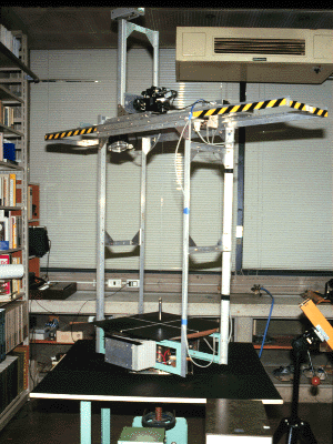
Record players were too weak for the purposes of experimentation, so in 1982, we made a rotating table designed for use in experiments. The motor was a 200W servo-motor combined with a 1/30 ratio reduction gear (Hitachi MD-0.2DGE). Revolution speed after reduction was from 6-60rpm (spec. value). When transmitting this revolving motion to the axis of the rotating table, there was a further 20% reduction, so the actual final revolving speed of the rotating table was from 5-50rpm. The controller that came with the set used a variohm to adjust the revolution speed, however it couldn't be used for fine adjustments, so we modified it to make it possible to adjust the revolution speed digitally. Regarding stability, there was a variation over short periods of approximately 0.1%, and over longer periods, there was a drift of approximately 1% (both figures are based on actual measurements). This level of stability is terrible compared to a record player, however the rotating table used without any problems for most experiments.
In order to measure the revolution speed, we fitted an aluminum disc to the bottom of the shaft of the rotating table and placed a photodiode and a phototransistor sandwiching the plate. When a hole made in the aluminum disc passes in front of the phototransistor, a pulse is created, and the revolutions are counted by keeping track of these pulses with a counter. By opening a number of holes in the disc, we could have measured the accuracy in shorter time, but since it is difficult to open holes at perfectly even intervals, we only used one hole. With one hole, it takes two periods' time to measure the revolution speed.
Slip rings of 4 channels were fitted to the upper part of the shaft for power supply. The motor's carbon brushes were in contact with brass rings in two places, but these rings were unsuitable for supplying a weak electric current. (The slip rings needed for a weak current cost more than the rotating table itself.) They were used for power supply for video cameras and other apparatus, as well as for opening and closing electromagnetic solenoids, such as those used in the Foucault's Pendulum and Ekman Spiral experiments.
A four-legged frame was fitted to the top of the rotating table (width approx. 50cm, breadth approx. 30cm), and the whole frame rotated with the table. Images of the rotating table were taken using a camera fitted to this frame. (Made by Iseya)

In experiments with rotating convection, a strong cooling device was necessary, however we could not fit it on the second generation rotating table, so we decided on making a new, larger table. The size of the rotating platform is 80x80cm, and space below the platform for mounting a cooling unit was also made. A stepping motor fitted with a 1/200 reduction gear (Oriental Motors, UPD599HG2-B) is used for driving force. The stepping motor rotates according to an input pulse, so it is possible to change the revolution speed by the order of 100 times. (with the servo motor, the order of 10 times was the limit). The maximum speed of the table is approximately 28 rpm.
In order to make full use of the precision of the unit, a steel belt (made by Dymco) was used to convey power to the shaft. The steel belt was used because there is always a minute loss caused by the join of a standard V-belt. The steel belt is a type used in precision instruments, and a pulley designed specifically for the steel belt was also necessary. As opposed to a V-belt, the pulley does not have a guide around its side, so if the rotating axes of the two pulleys are not precisely parallel, the belt comes off. Therefore, a design under which the angle of the motor shaft can be finely adjusted is necessary. (As this wasn't taken into consideration when making the rotating table, we had to make do by sandwiching metal plates in the motor mount).
The motor controller was made using a computer expansion board. Controllers are available on the market, however most of these are made with the positioning of machining tools in mind, and weren't designed for continuous rotation in one direction. By making a controller with a personal computer, it is theoretically possible to program any kind of movement. An 8255 parallel I/O was used to control the direction of rotation etc. and an 8253 timer was used to decrease the frequency of the internal clock and emit the pulse necessary for rotation. The slip rings used for the third generation table are designed mainly for power supply, and not for weak signals, but as the power consumption of the cooling device is relatively large, a maker-made slip ring (Litton Westrex, AC4598-6) were used for its power supply. It consists of 6 10A rings.
(Made by Iseya)